They are used in applications which do not require undervoltage protection. Technote 6 how to convert our start stop motor starter panel to an hand off auto.
 Wye Delta Starter Schematic Wiring Diagrams Title
 Wiring diagrams do not show the operating mechanism since it is not electrically controlled.

Motor starter wiring diagram start stop. They can be used as a guide when wiring the controller. C i m nc. Improper wiring can kill injure start fires burn out motors or anyall of the above.
The direct on line motor starter dol consist a mccb or circuit breaker contactor and an overload relay for protection. They show the relative location of the components. It is not difficult to learn the basic symbols.
Typically the contactor will be controlled by separate start and stop buttons and an auxiliary contact on the contactor is. Use transformer if you need to. Start stop 3 wire control.
How to wire a contactor and motor protection switch. Technote 7 what does the open wire banner mean on the sim alp2. Wiring diagrams bulletin 609 manual starters are operated by start stop push buttons mounted on the front of the starter.
A motor starter is a combination of devices used to start run and stop an ac induction motor based on commands from an operator or a controller. Using this method the current is balanced between the 3 poles on the overload. Motor starter schematic and wiring diagram.
Pilot light l2 4 2 3 pilot light start stop bulletin 1495 normally closed auxiliary contacts are required. You must watch this video. Then you connect the 2 motor leads to t1 and t3.
Technote 9 motor starter control panel naming revisions cp emsxx. Electromagnetic contactor which can be opened by the thermal overload relay under fault conditions. Typical wiring diagrams for push button control stations 7 start stop control wiring diagrams single station with motor stopped pilot light l1 start l2 i 1 stop 2 oi 3 n wol.
Figure 1 is a typical wiring diagram for a three phase magnetic motor starter. Both line and wiring diagrams are a language of pictures. T w 6.
3ph starter3ph motor line voltage control three phase 3ph motor starter controlling a three phase motor rev 08 aug 2006 the above wiring diagram assumes your magnetic starter has a 240v coil. Technote 8 revisions to industrial control panel trainer to make way for hmi and other improvements. Dol motor starter with 230v contactor coil.
How to wire a contactor and overload. The below wiring diagram shows how we would assemble a complete motor starter with a startstop button for a single phase motor utilizing a 3 pole contactor. In north america an induction motor will typically operate at 230v or 460v 3 phase 60 hz and has a control voltage of 115 vac or 24 vdc.
Starting a three phase motor.
 Wiring Diagram For 4 Pin Ke Light Switch Mega Wiring Diagram
  Basic Wiring For Motor Control Technical Data Guide Eep
  Electrical Contactor Diagram Wiring Diagram Fascinating
  3 Phase Contactor Wiring Diagram Start Stop Fresh Motor Starter
  Start Stop Contactor Wiring Diagram Elegant Eaton Contactor Wiring
 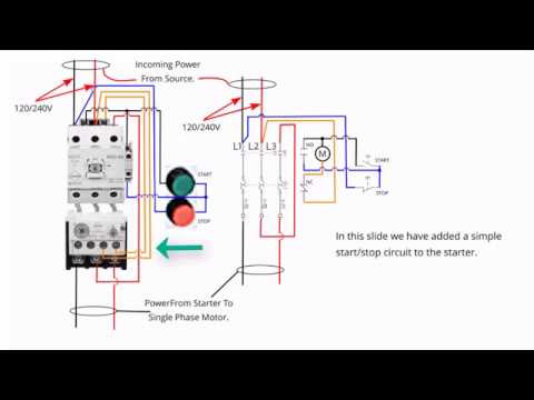 Start Stop Wiring Diagram Pdf Wiring Diagrams
 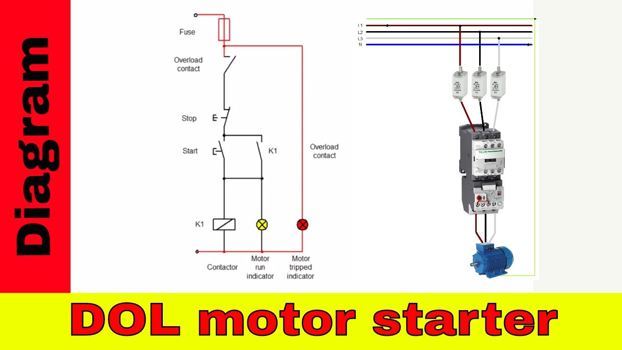 Motor Starter Wiring Wiring Diagram Section
 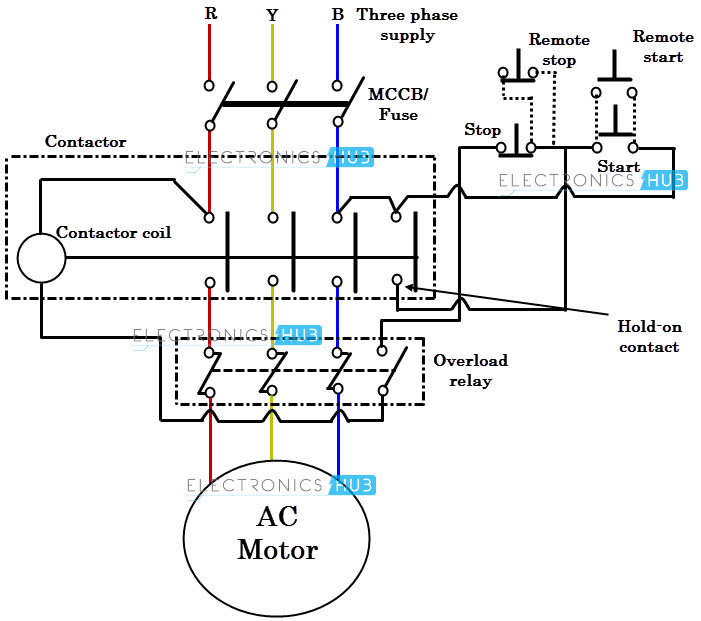 L T Dol Starter Circuit Diagram Schema Wiring Diagram Wiring Diagrams Contactor Wiring Diagram Library